ABSTRACT
Transformer manufacturers can be faced with difficult decisions when it comes to large-scale investment. Uncertainty can delay large-scale investments resulting in equipment with older technology and inefficient work procedures being left in production. In this paper the authors expose a method where re-alignment of existing machines (through the integration of machine technologies such winding mandrels, wire flattening, cold welding, etc.…) can be done with incremental investment allowing companies to improve current processes while managing capital investment. The application of the Staged Investment method proposed in this paper can be adapted to other peripheral transformer component manufacturing lines such as cores or tanks with excellent results.
Index Terms—Transformer winding, Staged Investment.
I. NOMENCLATURE - DEFINITIONS
Transformer coil: High Voltage and Low Voltage conductive
parts of the transformer. Electrical energy is transferred
between them.
Staged Investment: gradual use of funds to implement
new technologies in a transformer manufacturing plant.
II. INTRODUCTION
The idea of intelligent and automatic machine operation
are broad concepts in transformer coil production. They can
mean different things to different people, depending on
their current level of technology. As part of this presentation,
MTM and H-J will present various modern concepts
associated with intelligent and automatic machine operation
that can be included in future machine considerations
by transformer manufacturers, regardless of their size and
the investment capacity. These concepts are applicable
when considering new machines but can also be applied
with respect to incremental improvements that can be
made to existing equipment. These features can have a
significant impact on the quality of the coil being produced
while improving equipment productivity.
This paper will illustrate the positive economic impact and
benefits of these concepts. Overall effects will vary depending
on the user. We encourage the reader to make his own
determination of real benefits based on the concepts
presented. Many of these solutions have been implemented
by transformer OEM’s globally, with a high degree of
success.
III. DEVELOPMENT OF THE CONCEPTS
Winding Machines can be divided into five classifications
of design:
- Low Voltage Foil
- High Voltage Foil
- Distribution Wire
- Power Wire
- Combined LV Foil and Wire
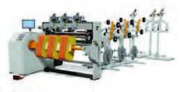
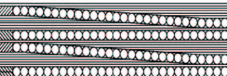
Pictures below illustrate the typical standard product lines
using some of these machine designs. Production capacity
in terms of number of units and kVA size determines type
and quantity of the winding machines. Fig. 1. Typical Low Voltage Foil Winding Machine.

A. Combination of winding machines
Before making capital investments in separate HV and LV
winding lines, combined machines (designed to wind foils
and rectangular or round wires in the same machines) can be
a good solution to save time and investment capital with
production requirements are small. The addition of wire
winding to a foil-winding machine are small when considering
the price of a separate wire winding machine. Many
“state of the art” features are present in this first step to the
Intelligent Manufacturing Line:
The cost of adding HV wire feature to a LV winding machine is
less than 40% of adding a new HV winding machine to the
production line (cost dependent on the number / type of
wires)
- Wires are guided onto the coils by PLC based automatic
control systems, eliminating manual control of tension by
the operator. This adds important quality value to the winding
mainly to get the standard damage curve requirements
per IEEE C57.109 for short circuit withstand capacity.
- Likewise, the coils are guided through the machine with
automatic alignment and tension control. It improves the
short circuit capacity by making easier the alignment of the
HV and LV windings.
- Machine’s PLC ensures the winding is done to program. No
need to make further tests on turns ratio. This saves time and
allows operator to concentrate in primary processes building
quality into the process.
- In these machines, as in any last generation winding
machines, the operator faces front to the coil being wound,
with insulation, foils and wires feeding from the back of the
machine. This way the winding operator controls easier
quality facts like windings alignment and the need to refill
any material as he is positioned in front of the pay offs.
- Production time is reduced through elimination of transport
of the LV coil to the HV winding machine since the HV coil is
applied to the LV winding in the same machine. Combined
winding machines reduce production time up to 30%.
-
Combined machines reduce the number of windings
flowing in production (from 2 pieces to 1) which is part of the
lean manufacturing concept to reduce work in process (WIP).
Less time is used to handle the coils, stage the coils between
operations, which reduces handling and the potential of
damage.


The features integrated into these machines can be standard
or advanced. To begin with our incremental improvements
method, a standard machine can be introduced using only
single HV and LV coils winding systems and leaving
multi-winding systems for further incremental steps. See B.
below. However, combined machines can gain complexity
including multi-coil winding systems. Figure 4 shows a
typical layout of a large combined machine for large distribution or small power transformers using 2 parallel foils and up
to 6 rectangular wires.


B. Multi-coil production systems and setup of production
cells in manufacturing
Once the volume of production increases, it gets convenient
to move to our second incremental improvement: the
multi-coil production concept and introduction of the
production cells. This method takes into consideration the
balancing of time to make LV vs. HV sections of the coil. This
is a scaling up concept that builds on the idea of having a
combination machine.
Multiple coil machines are very useful mainly for HV coils
due to the fact production time for HV coils may be 3 or 4
times the production time of LV coils (in some cases). Initially
the machine may take a little longer set-up time, but once in
operation, every turn of the machine will produce multiple
coils. This results in production time per coil being reduced
by about 1 divided by the number of coils mainly in small
kVA rating transformers where the number of turns is high.
Advantages are evident in the productivity of the process and
the use of less machines for the same production volume.
Typical reduction of production times when using triple HV
winding machines is up to 60%, again a function of number
of turns: the larger it is, the higher the productivity gains.
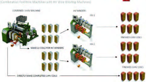
The production cell concept provides a method for balancing
HV and LV coil production, which is a challenge due to the
time differential in production of the two. This concept
consists of combining HV winding machines with compact or
combined HV/LV winding machines to achieve continuous
production of both windings. While the combined machine
produces many LV coils to feed the HV winders, it can also
produce complete (HV plus LV) coils. Production of the LV
coils can be scaled with production of the complete HV/LV
coils in order to provide a balance in production of the coils,
thus generating uninterrupted supply of both. Not having
idle time easily reduces 20% of the total windings production
time per day.
Data from each machine or group of machines can be collected
and downloaded to a central location for analysis of the
production flow.
Insight to the Production Process can be determined:
- Costing of each coil
- Trending in processes
- Bottle necks in the production process
- WIP management
- Variations in operator and machine performance
C. Automatic insulation cutting and tensioning systems
With older winding machines (without re-alignment) it can
be difficult to control tension between HV layers of the coil.
With LV coils “manual” or “non-uniform” tension is provided
resulting in loose coils with poor short circuit strength. With
newer machines insulation papers are tensioned and
positioned near the coil so the operator can gain access
during the winding. Uniform tension is applied. Machines
can be equipped with an automatic cutting process of the
insulation paper further speeding up the production
process.
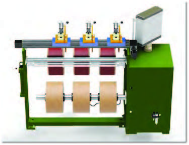
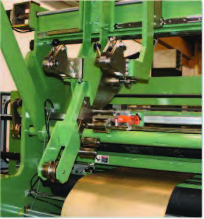
As the next incremental system improvement, insulation
tensioning systems improve short circuit strength to the coil
assembly for a relatively low investment. Figures below
illustrate typical paper tensioning systems. Note that the
papers are tensioned equally across coils on the machine,
insuring equal tension within each coil. It must be reminded
short circuits are main failure cause for distribution transformers.

D. Closed Loop Wire Tensioning Systems
With older winding machines (without re-alignment) it is
common for round wire tension to be controlled with a
mechanical brake (and possibly other mechanical systems).
While this system provides tension to the wire, it is up to the
machine operator to determine if the tension is correct. This
is done by qualitative methods. With a closed loop tensioning
system the designer will be able set the required tension
range for a given conductor and the PLC system will maintain
the tension through the coil winding. This is an advanced
feature available on new winding machines. Keeping
constant the wire tension at a certain value, adds uniformity
to all manufactured windings assuring short circuit
withstand ability to the transformer.
E. The gradient insulation system, also known as
progressive insulation
The gradient insulation system employs the use of a continuous
insulation strip to vary the thickness of the insulation
across the winding layer according to the program.
This method allows the appropriate insulation thickness to
be used where there is greatest difference in voltage potential,
and less thickness where there is less potential. The net
result is a reduction in coil diameter, with corresponding
reduction in the amount (mass) of insulation used. Figures below show the Gradient Wrapping representation. Total
winding material savings (conductor plus insulation)
arounds 15%. Also, because the insulation layer is being
wound at the same time as the wire section, the time to wind
the HV section can decrease by as much as 30%.
This improvement is of great benefit to manufacturers using
windings with gradual or reduced insulation mainly for
grounded wye connection of power transformers.

F. Wire flattening – 1 or 2 wires:
Round wire flattening is a well-known process providing
important benefits in HV coil designs for distribution transformers
such as:
- Reduction in air gap between turns, improving the space
factor. This causes a reduction of the core window, reducing
core losses.
- Reduces the electrical stress between layers by reducing the
number of turns per layer. In some cases, reduction of the
insulation thickness can be achieved.
- Substantially increases the surface of the conductor in
contact with the insulation paper, thus increasing the short
circuit strength by improving the adherence between layers.
- Reduction of the radial coil build by reducing the wire thickness
by up to 20%. This means narrower core windows, less
materials and losses. Total cost reduction between 5 to 10%
can be reached by adding wire flatteners to the coil winding
production line.
Wire flatteners can be added to existing machines.
G. Cold Welding:
Cold welding of conductors, leads and terminals was developed
to eliminate the need for heating of conductors either
to join two conductor spools or to join conductors and terminals.
In many cases this can require joints of different materials.
Cold welding allows joins between copper to copper,
copper to aluminum or aluminum to aluminum.
This incremental investment can reduce production time;
however, its main impact is in the quality and long-term
duration of the joins as e.g. many of the copper-aluminum
joins are affected with the pass of the time by galvanic
reactions in the contact areas creating hot spots that reduce
transformer’s life.
The process is clean, quick, requires no cooling time, and can
be added to existing machines. This process can also be
provided by a stand-alone machine that is portable for transport
between work centers. Cold Welding systems can be an
integrated foil and lead cleaning system and vacuum for
removal of debris. Design parameters for the cold-welding
process can be computer controlled and integrated with the
winding process.
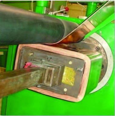
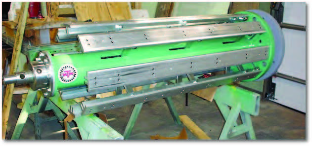
H. Winding Mandrels and Forms:
Rectangular, oval and round expanding mandrels are necessary
tools to produce compact coils for distribution and
power transformers. Cost of these tools varies as a function of
the transformer size. In general, the investment required
increases exponentially with the kVA size of the transformers.
Pneumatic or mechanically expanding versions are
available. Quality mandrels keep windings alignment and
tension helping to maintain transformer damage curve and
winding dimensions within tolerance. It should be noted
that rectangular mandrels can be designed with 2 or 4 way
expansion (independent).


IV. CONCLUSIONS
The methodology developed in this analysis illustrates how
transformer manufacturers can employ the Staged Investment
process to gradually implement Intelligent Automatic
Transformer Coil Manufacturing Lines.
For those cases where manufacturers have low investment
capacity, the proposed method of investment allows the
manufacturer to start a plan with periodic investments that
finally takes him to a completely automated production line
gradually reducing costs and improving quality.
By using these methods and according to the experience of
the authors, high tech production can be achieved by small
or large manufacturers at their own pace of investment.
V. REFERENCES
L. Wang, S. Wang “Is staged financing designed for alleviating
risks or agency problems?” in Handbook of Business and
Finance. Nova Science Publishers, 2009, ISBN
978-1-60692-855-4
VI. BIOGRAPHIES
Orlando Giraldo was born in Pereira Colombia, on Feb 3,
1953. He graduated from the Technological University of
Pereira. His employment experience included 13 years at the
ABB Distribution Transformers Plant in Pereira and 13 years
at the SIEMENS Distribution and Power Transformer Plant in
Bogota Colombia. Fields of experience include design,
production, tests and sales. He has also worked for many
years in the Transformer Standards area in Colombia. He has
been teacher of Electrical Machines at the Technological
University of Pereira and at the National University of Colombia
in Bogota. He is since 1999 with The H-J Family of
Companies; currently Senior Consulting Engineer.
Gord Atamanchuk, P.Eng. has worked in various positions
in machine development, manufacturing, and sales since
graduating from the University of Manitoba with a Bachelor
of Science in Mechanical Engineering in 2000. Gord’s
involvement in product design, testing, manufacturing, and
service / support gives him unique expertise on the machine
development process and the role technology plays in this
environment. Gord is currently General Manager of Micro
Tool & Machine Ltd. (MTM), an engineering firm specializing
in custom machine design and automation to support
various industries (including the transformer industry).
Download Resource